medm screens
modbus provides example medm .adl files in the modbusApp/op/adl directory.
modbusDataTypes.adl
The following is a screen shot from an IOC running the testDataTypes.cmd and testDataTypes.substitutions files, communicating with a Modbus Slave Simulator. These are the ao/ai records using the asynFloat64 interface. It shows that the output and input (readback) records agree.
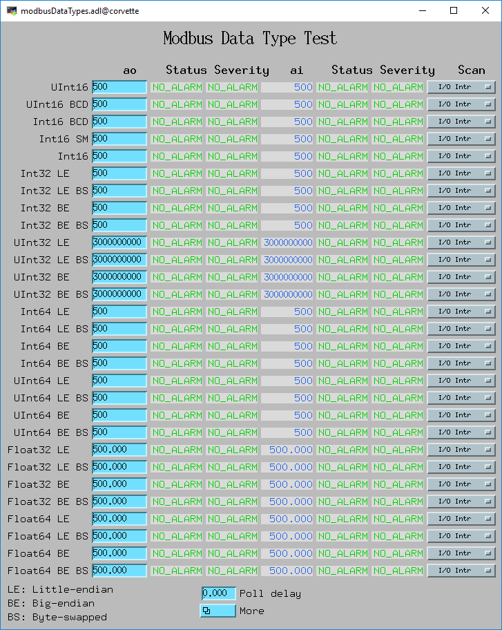
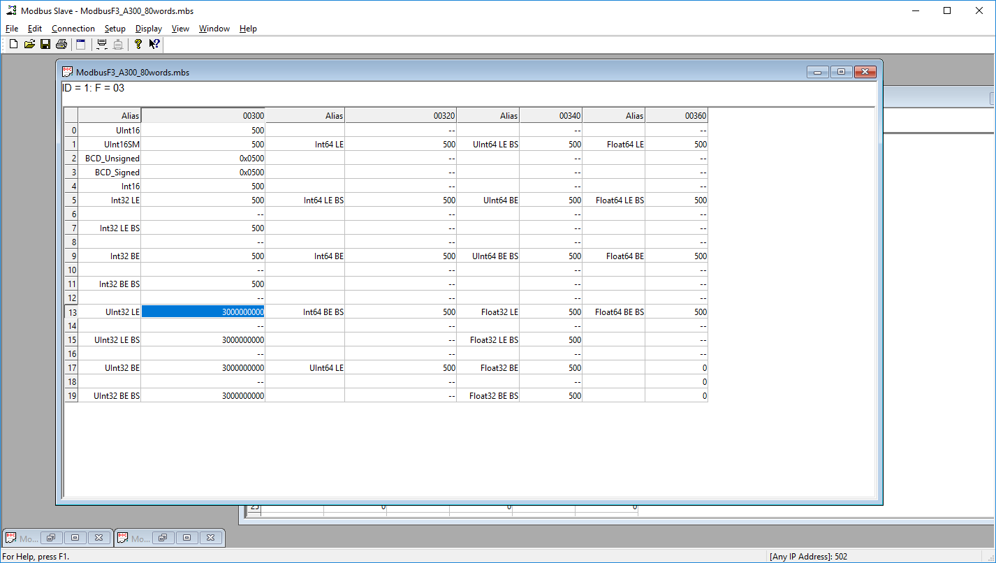
The following is a screen shot from the Modbus Slave Simulator communicating with the ao/ai records shown above. The values shown in this screen agree with this in the medm screen, showing that each Modbus data type is being communicated correctly.
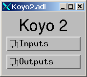
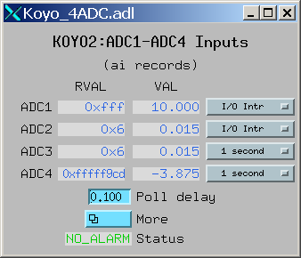
The following are screen shots of these screens from an IOC controlling a Koyo DL205 PLC.
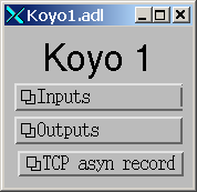
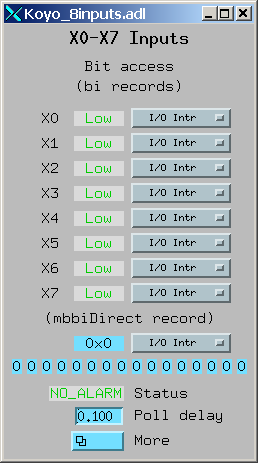
Koyo_8inputs.adl
Inputs X0-X7 read as discrete inputs (function code 1).
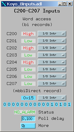
Inputs C200-C207 read as register inputs (function code 6).
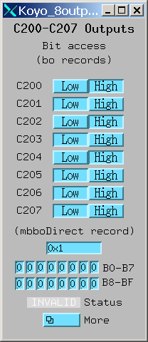
Koyo_8outputs.adl
Outputs Y0-Y7 written using register access (function code 6).
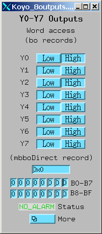
Outputs Outputs C200-C207 written using bit access (function code 5).
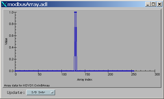
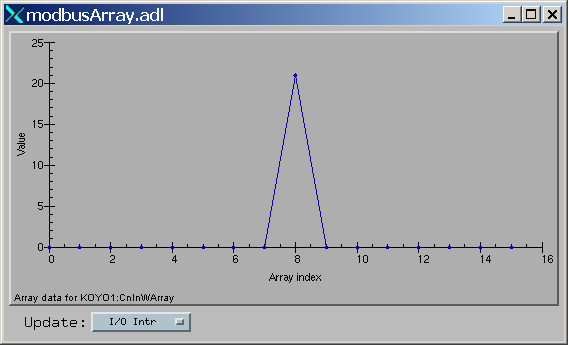
modbusArray.adl
Inputs C0-C377 read using a waveform record and coil access (function code 1).
Inputs C0-C377 read using a waveform record and register access (function code 3).
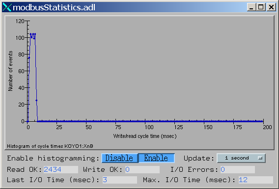
modbusStatistics.adl
I/O statistics for the Modbus driver that is reading inputs X0-X37 using register access (function code 3). The histogram is the number of events versus TCP/IP write/read cycle time in msec.